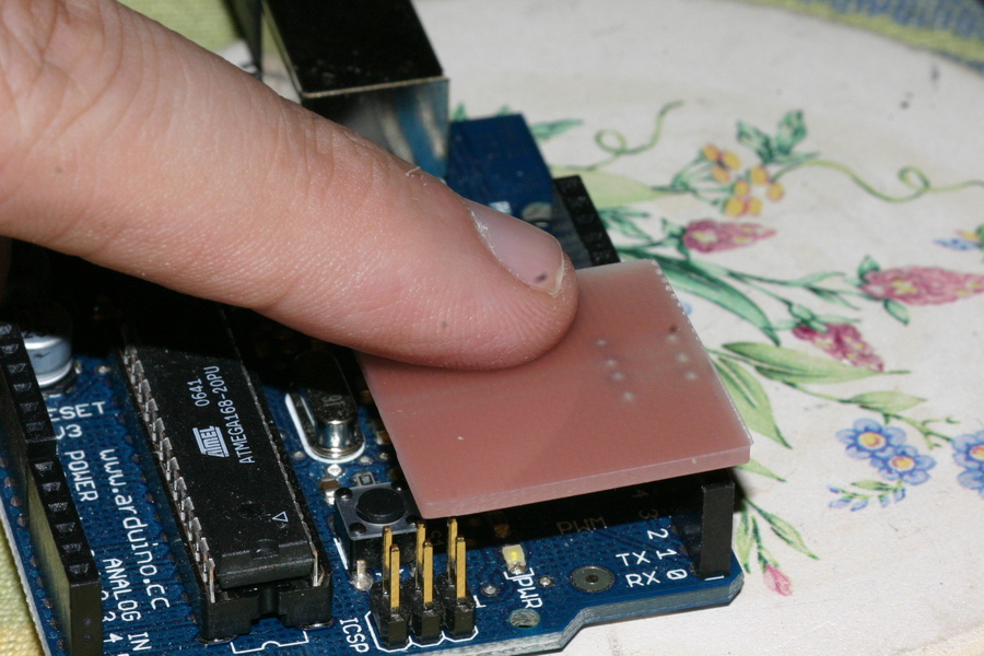

The sensors are each about 1" by .5" and are connected to the arduino by a 3-pin header. The components on the board are very simple -- two 1M resistors. With a combination of software running on the microcontroller and in the PC, the sensor is made into a virtual slider.

The principle of operation is simple: placing a fingertip near the copper pad -- and the far side of the circuit board is close enough -- changes the capacitance enough to measure. The measurement procedure is as follows:
- The pin is discharged to close to 0V by setting the sense pin to an output and putting a logic LOW on it.
- The pin is changed to input mode and a 1M pull-up resistor is enabled.
- A tight loop counts the number of iterations until the pin reads HIGH.
- After reading both sensors in this way, transmit both sensor counts to the PC.
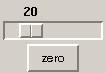
In my setup, this gives a value typically from 16 iterations (no nearby finger) to 24 iterations (finger pressing on top side of sensor board). A 200-item window of past samples is taken, and that furnishes the minimum and maximum touch values. When a sensor value higher than the minimum value is seen on at least one sensor, a touch is registered. If the touch is only on one sensor, then the slider is 0% or 100%. Otherwise, it is an intermediate position indicated by the ratio between the two sensor values.
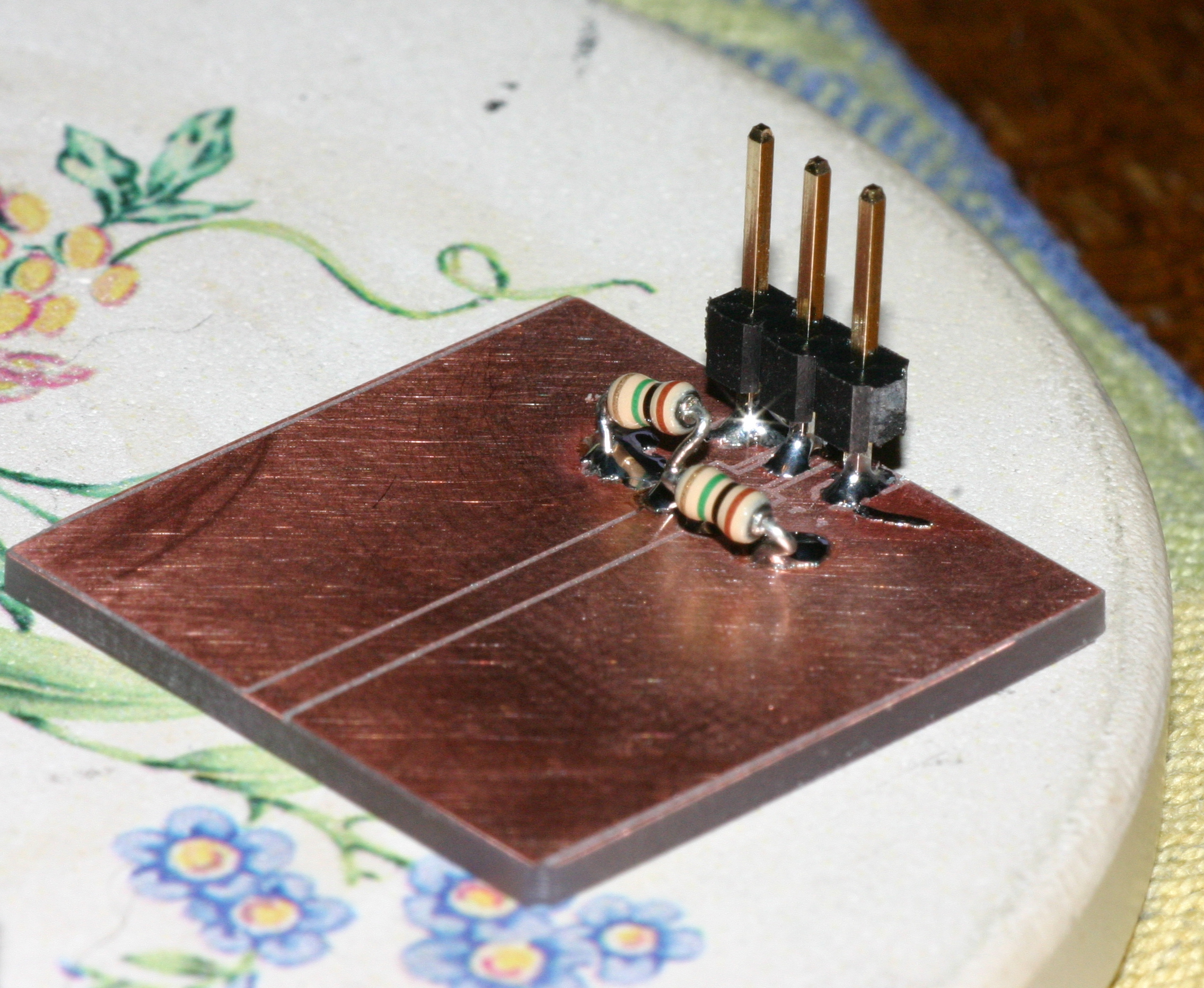
One interesting thing about the board is that I milled the holes only part way through, and just stuck the "through hole" components into the blind holes before soldering them. This way the touch surface is completely uninterrupted.
This approach can be expanded to more pads, taking (N+1) I/O pins. I'm presently toying with making an 8-pad board run by a dedicated avr.
Files currently attached to this page:
| cap.pde | 515 bytes |
| cap.py | 1.7kB |
Entry first conceived on 29 August 2008, 0:49 UTC, last modified on 15 January 2012, 3:46 UTC
Website Copyright © 2004-2024 Jeff Epler