The old setup had the home switches on unshielded wires running next to the motor wires inside split-loom tubing, connecting to screw terminals inside the controller box. This didn't seem to cause much trouble, but I never liked the setup much, and the screw terminal board was homemade without provision for decent mounting, not to mention being designed for the pluto-p pinout.
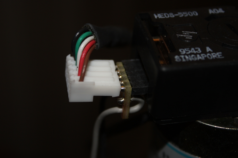
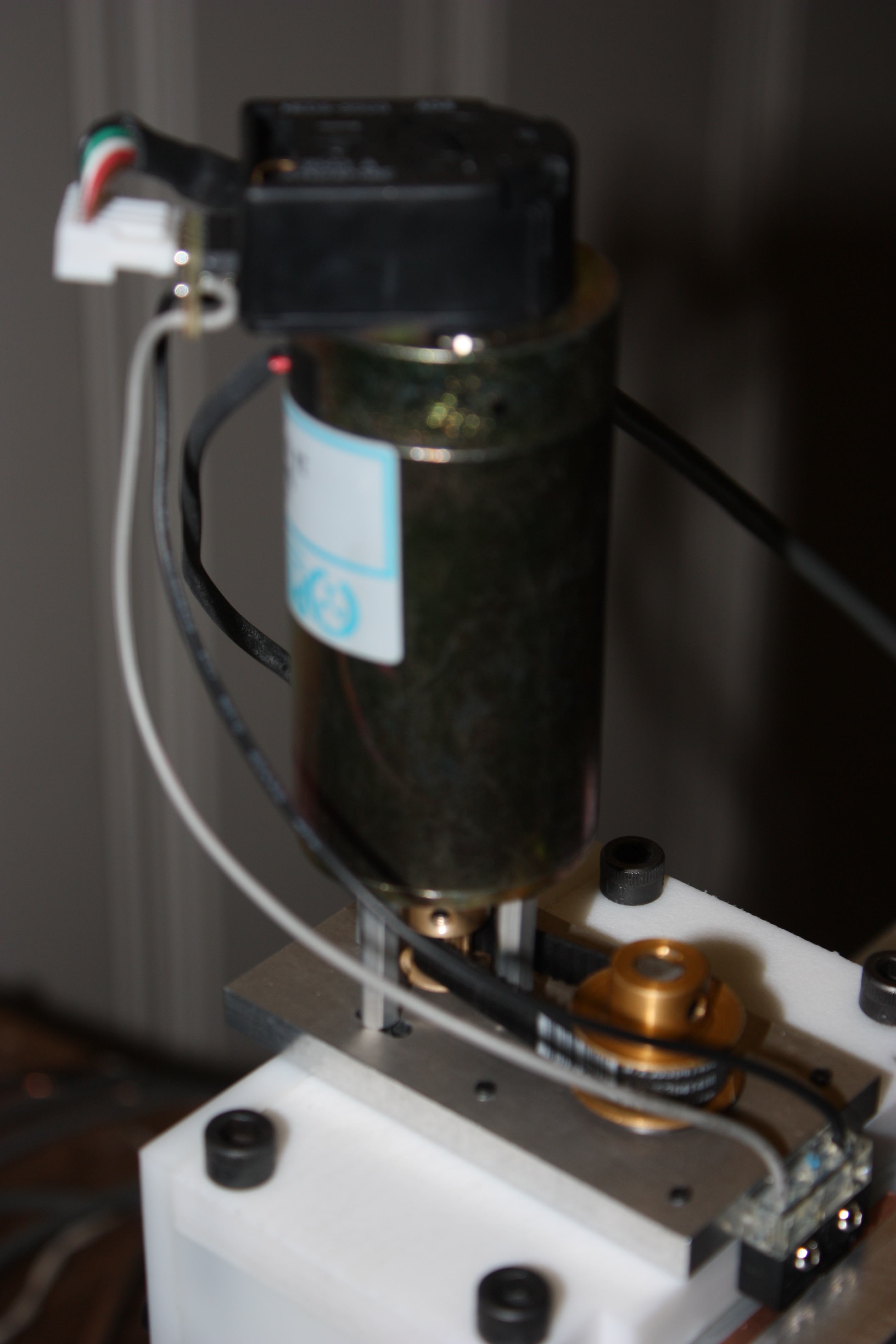
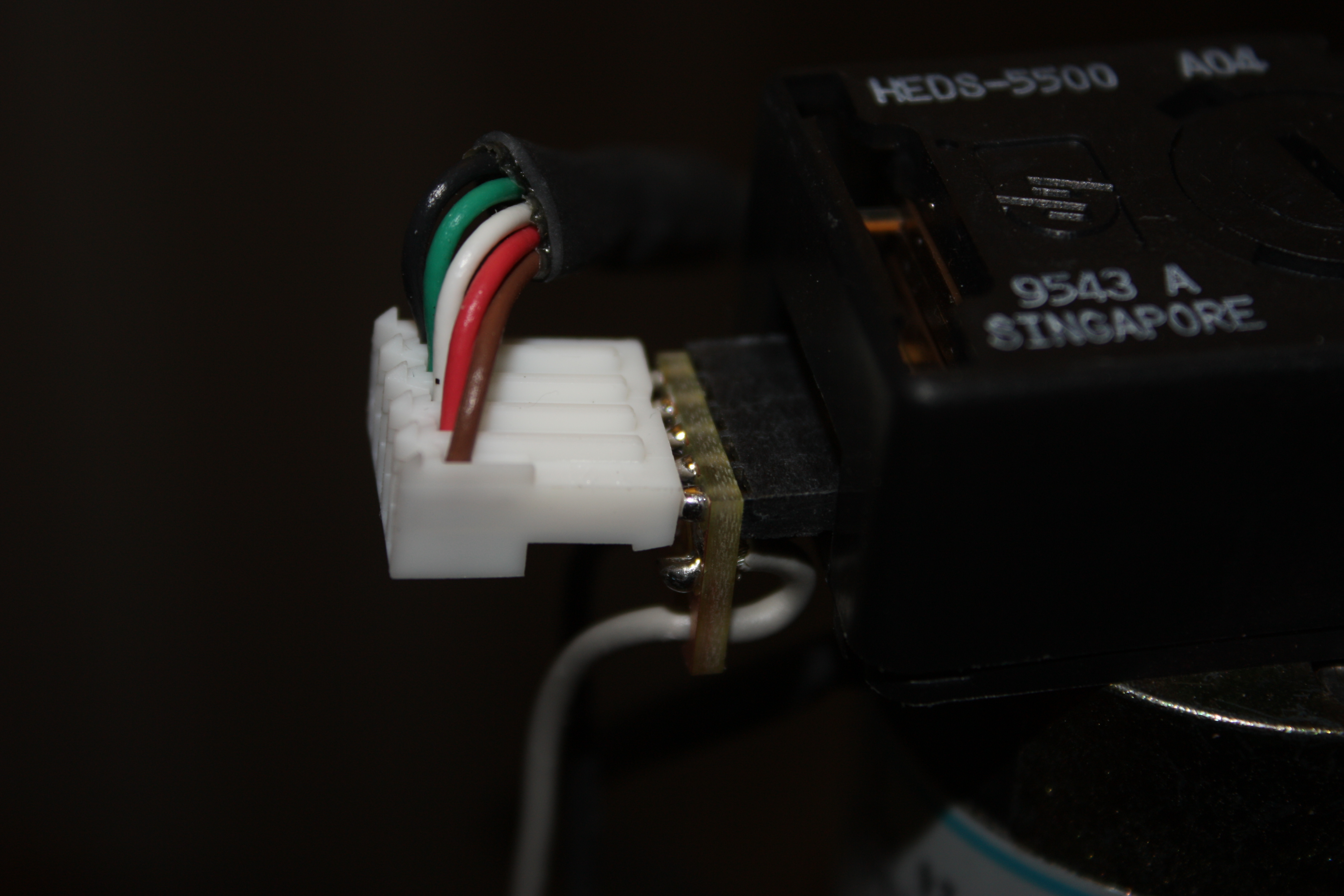
Then I realized that in each shielded encoder cable I had a spare wire--the encoders don't have index, but there's a wire present for it. I ordered some slightly special female headers with long legs, and made a couple of tiny boards (<.25 in^2) which would allow me to solder a switch to GND and INDEX positions, passing the others through from encoder to mesa hostmot2.
Because the X and Y home switches actually both move with the X axis, I wired that connector as two NC switches in series. (I designed the board for two NO switches at 4 pads, so I just used one pair holes and series-connected the switches outside the board)
I haven't tested the homing repeatability with the servo motors, but I have every reason to believe it will be good enough. It won't be single-count-perfect, since I don't have index signals; but they should be as good as with steppers, though.
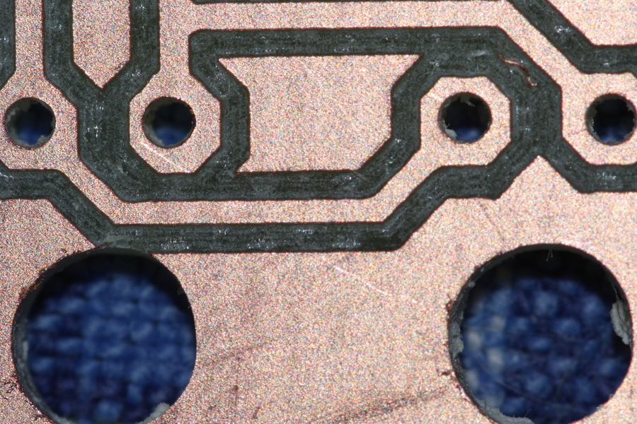
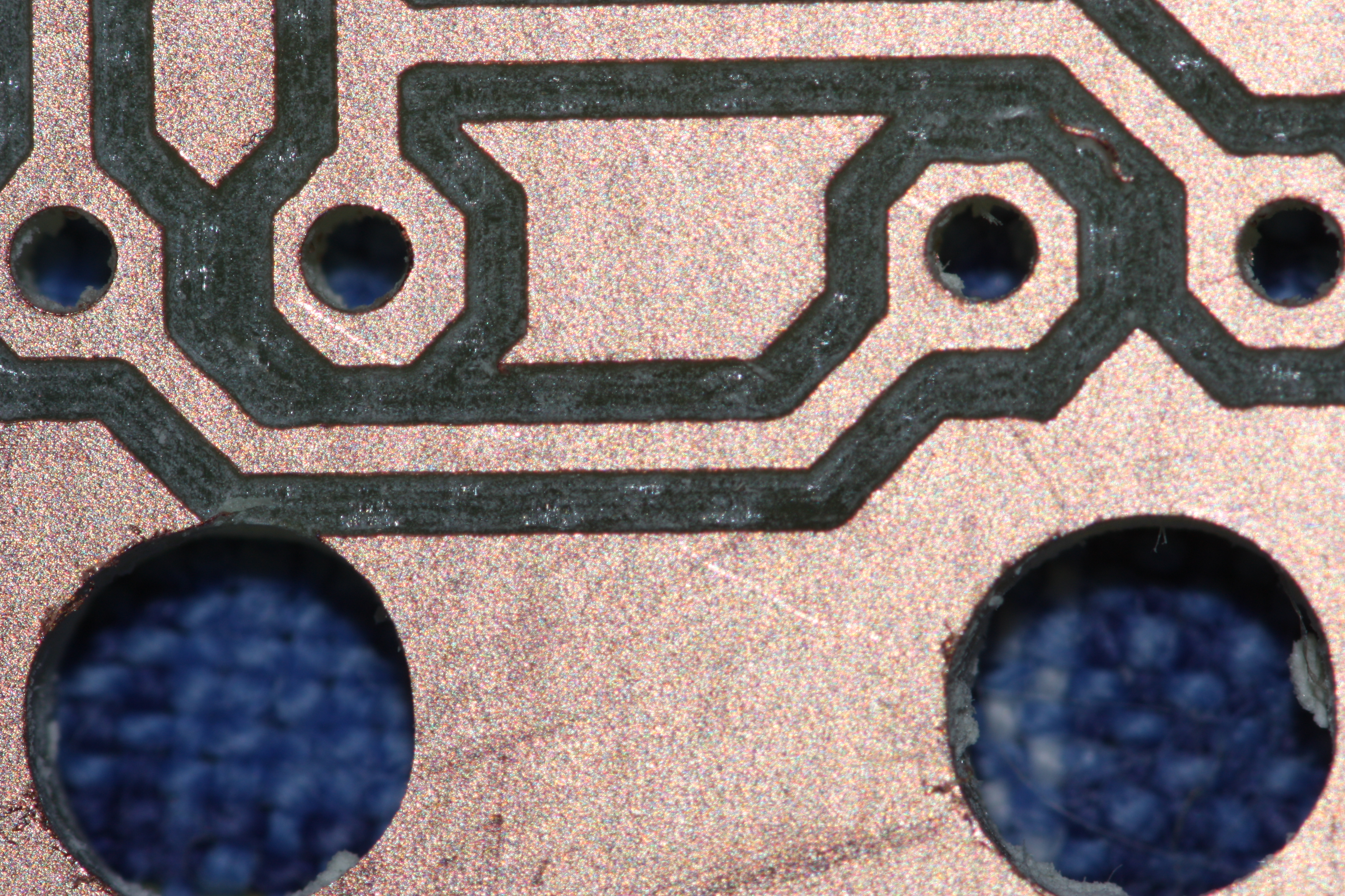
I haven't hooked up the tool length sensor yet. Since I now use only tools with depth-setting rings, I hope that I'll be able to simply touch off with the trace isolation tool and assume that the subsequent drills and mills are the same length. This is the approach I used on these boards, and it worked out fine.
The drills on some pads ended up somewhat off-center. I'm not sure why this is, yet. I hope that it's not encoder noise, but I also don't want to learn that it's backlash! Anyway, it wasn't so severe as to hurt the usability of these boards.
One last note: if you accidentally use the A or B encoder phase as a home switch signal, you will get some really weird behavior when you try to home, as emc reads an essentially random value each servo cycle while the motor is moving.
Entry first conceived on 20 August 2009, 22:48 UTC, last modified on 15 January 2012, 3:46 UTC
Website Copyright © 2004-2024 Jeff Epler
