
This is the kind of problem we can solve with technology! If I can check the status of my network without looking at a computer, then I'm bound to start arriving at the office on time.
Now, I already had most of the pieces of this project laying around:
- 2 xbee wireless modules
- xbee explorer usb (xbee-usb bridge)
- blinkm blaster rgb led cluster
The software on the avr end is very simple (programmed in the arduino environment): if no characters are received after a timeout, increase the alert level. Otherwise, set the alert level based on the received character. The 4 alert levels are dim green (OK), cyan, yellow, and red (ERROR).
On the PC end, things can get as complicated as you like. I've written a fairly extensible program that has a number of checks to make; each check is simply a python function, and can have a different check interval. When checks fail, the function is re-run more frequently so that the condition will show as "cleared" soon after it's fixed. One of the "checks" is for files in the ~/.checks directory, so arbitrary programs can just create a file if attention is required.
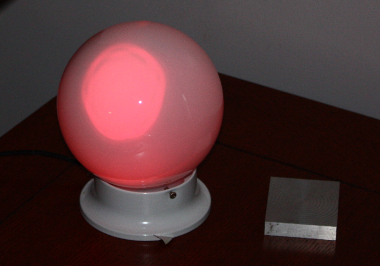
Updated, 20090307: I made a more permanent home for this gizmo: a lamp fixture with a frosted glass ball. I also solved the "two wall wart" problem by soldering a jumper from the funnelio's +5V to the BlinkM.
Problems I've seen so far included:
- My xbee modules were very old and had to be firwmware upgraded. I couldn't get this to work in wine or virtualbox, so I actually booted a WinXP desktop before I got it working (and even there the process appeared finicky). After this, though, I could change the settings using AT commands in linux.
- The advice to solder RTS to D3 appears to be wrong, because the Arduino pc-side software strobes DTR (not RTS) to reset; I didn't take the time to re-solder it, but instead just manually ran an RTS-strobe program before and after each reprogramming
- There are occasional data losses or bit errors that cause the alert level to change--I'm not sure which. What I observe from time to time is that for a few seconds the LED will shift from dim green to cyan and then back, even when check.py doesn't say it sent anything other than 0s. Data has to be lost for 20 seconds before the module increments the alert level, but data should be sent about 10 times a second, so this means 200 transmitted bytes must get lost. On the other hand, a bit error should also be corrected about 1/10 second later if the next bit is sent properly.
Files currently attached to this page:
| checks.py | 3.3kB |
| redalert.pde | 2.1kB |
| xbee-setup.py | 1.5kB |
Entry first conceived on 31 January 2009, 16:29 UTC, last modified on 15 January 2012, 3:46 UTC
Website Copyright © 2004-2024 Jeff Epler